Joints
Joints in dyn4j represent mechanical connectors between bodies. All joints are pair-wise, meaning they join two bodies together, with exception of the PinJoint. Bodys can participate in any number of joints to produce new behaviors.
Typical Joints
These joints represent the standard set of mechanical connectors.
Distance Joint
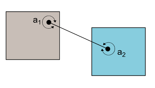
The DistanceJoint class represents a fixed distance between two bodies. The bodies are allowed to rotate freely about the anchor points. The DistanceJoint class can also act like a spring-damper with specified fixed distance is a target distance (or rest distance). In addition, the DistanceJoint can also be configured with a maximum and minimum distances to act more like a rope.
This joint is defined by supplying the anchor points, \(\vec{a}_1\) and \(\vec{a}_2\), in world coordinates.
Revolute Joint
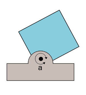
The RevoluteJoint class represents a joint that only allows rotation between the joined bodies. This class also supports the use of a motor and limits. The motor can be used to apply motion between the bodies and the limits can be used to limit the angle between the two bodies.
The angular limits are relative to the initial angle between the two bodies.
This joint requires one world space anchor point, \(\vec{a}\), which is used as the pivot point.
Weld Joint
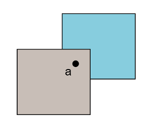
The WeldJoint class represents a joint that “welds” two bodies together. This can be used to fix two bodies together as one, then removed to simulate destructible bodies. When bodies are joined by a WeldJoint their relative rotation and translation is constant (determined by the initial configuration).
Like the DistanceJoint class you can add a spring-damper. However, this acts as a rotational spring damper instead of a linear spring damper.
This joint requires one world space anchor point, \(\vec{a}\), which is used as the weld point.
Prismatic Joint
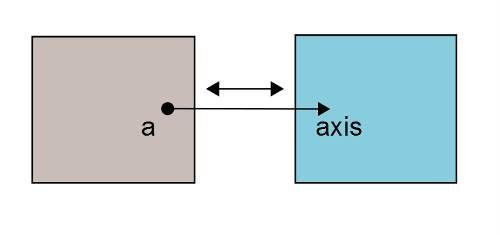
The PrismaticJoint class represents a joint that allows bodies to translate freely along an axis. The system, the two bodies together, can rotate freely, but the two bodies cannot rotate individually. Like the RevoluteJoint, this joint allows for motors and limits. The motor will drive the linear motion along the axis toward the given speed and the limits will limit the linear motion along the axis.
This joint requires one world space anchor point, \(\vec{a}\), which is used as the pivot point to prevent rotation and a world space \(axis\) used as the allowed translation axis.
Pin Joint
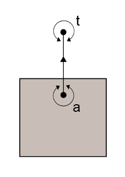
The PinJoint class is the only unary joint in dyn4j. It’s designed to pin an object to a given world space point. The PinJoint creates a spring-damper distance joint at a given world space point on the body and drives the distance to zero.
The
PinJointwas calledMouseJointin versions prior to 3.2.0.
This joint requires the anchor point, \(\vec{a}\), in world coordinates and the spring-damper values. The PinJoint.setTarget(Vector2) method should be used to update the target point, \(t\), to drag the body to that position.
Pulley Joint
The PulleyJoint class represents a joint connecting two bodies by a fixed length “rope.” The PulleyJoint only limits translation along the “rope” axes and can limit the length of the “rope.” Setting the ratio to something other than 1.0 causes the pulley to emulate a block-and-tackle.
This joint requires a world space fixed point, \(\vec{pa}_1\) and \(\vec{pa}_2\), and a world space body point, \(\vec{a}_1\) and \(\vec{a}_2\) for each body.
The lengths of the “ropes” are computed by:
\[\| \vec{pa}_1 - \vec{a}_1 \| = ratio * \| \vec{pa}_2 - \vec{a}_2 \|\]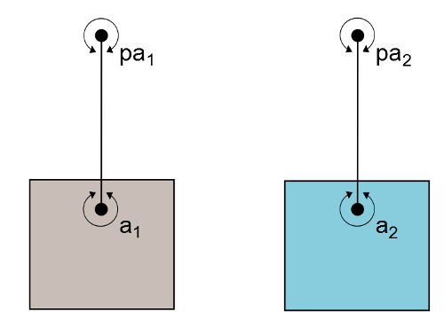
Wheel Joint
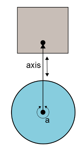
The WheelJoint class represents a joint connecting two bodies where the bodies are allowed to rotate about the given anchor point and translate about the given axis. The translation portion of the allowed motion has an optional spring damper. This is an ideal joint for vehicles. The motor for this joint is a rotational motor.
This joint requires a world space anchor point, \(\vec{a}\) (the pivot point), and a world space (normalized) \(axis\) for the allowed translation.
This joint can be thought of as a combination of the revolute and prismatic joints.
Angle Joint
The AngleJoint class represents a joint connecting two bodies limiting their angles. This is similar to the RevoluteJoint when limits are enforced. When the angle limits are equal this joint will force both body’s angles to be identical. Regardless of the limits, the bodies are allowed to translate freely.
The angular limits are relative to the initial angle between the two bodies.
Setting the ratio field of the AngleJoint allows the bodies to rotate at the given ratio of one another. This creates a gear-like effect. If limits are used in conjunction with the ratio, the ratio will be ignored when the joint reaches a limit.
This joint only requires that the two joined bodies be given, initially defaulting to equal limits.
Other Joints
These represent joints used for non-mechanical behavior.
Friction Joint
The FrictionJoint class represents a joint that attempts to drive the relative motion between the bodies to zero. The maximum force and torque members are used to limit the rate at which the motion is driven to zero.
This joint only requires one world space anchor point which is used as the pivot point for adding friction to the relative angular motion.
Motor Joint
The MotorJoint class represents a joint that uses motors to move a body. The application sets a target position and rotation (relative to the other body) and the joint attempts to reach that state. The maximum motor torque and force can be limited. This joint is better for character movement since it still allows the bodies to interact naturally with the world.
This joint only requires two bodies (the initial linear target is the first body’s center of mass). Typically one of the bodies is static. The linear and angular targets are relative to the first body’s center of mass and angle.
Tags
Bible
Collision Detection
Constrained Dynamics
Contacts
EPA
Equality Constraints
GJK
Game Development
Java
One God
OpenGL
Physics
SAT
dyn4j
Categories
- 23 Blog
- 8 Collision Detection
- 19 Game Development
- 46 News
- 39 Release
- 10 Constrained Dynamics
- 11 Physics
- 1 Bible
Recent Posts
Posts by Year
2024
2022
2021
- Simple Polygon Simplification
- A Faster Broadphase in dyn4j 4.0.0
- WordPress to GitHub Pages
- dyn4j.org Moved to GitHub Pages
- Version 4.1.0
2020
2018
2017
2016
2015
2014
2013
2012
- Version 3.1.2
- Version 3.1.1
- Algorithmic and Architectural Gaming Design: Implementation and Development
- Version 3.1.0
- Version 3.0.3
2011
- dyn4j Project Setup Video
- Version 3.0.2
- Contact Points Using Clipping
- Version 3.0.1
- Version 3.0.0
- How A Differential Gear Works
- Prismatic Constraint
- The dyn4j TestBed Now Uses JOGL
- Version 2.2.3
- Version 2.2.2
2010
- Angle Constraint
- Line Constraint
- Pulley Constraint
- Weld Constraint
- Version 2.2.1
- Max Distance Constraint
- Version 2.2.0
- Version 2.1.0
- Distance Constraint
- A Few Services Ago
- Version 2.0.0
- Version 1.1.0
- Equality Constraints
- Documentation Update
- Point-to-Point Constraint
- dyn4j Is Released!
- Version 0.7.2
- EPA (Expanding Polytope Algorithm)
- GJK, Distance, Closest Points
- GJK (Gilbert–Johnson–Keerthi)
- SAT (Separating Axis Theorem)